
Project: The $5 Cracker Box IPod Amplifier
This weekend we built a IPod amplifier to power a small 8ohm speaker for an art project that one of my good friends was doing. Her project involved a metal sculpture that speak a manifiesto to anyone that walked in front of it.
I found the Amp Schematic in the latest MAKE magazine 09 - The $5 Cracker box amplifier.
It ended up costing closer to $20 CAN in parts because when you buy capacitor and resistor you have to buy them in bundles packages of 20 or so. In the end I have enough spare parts to build 5 of these amps for $20.
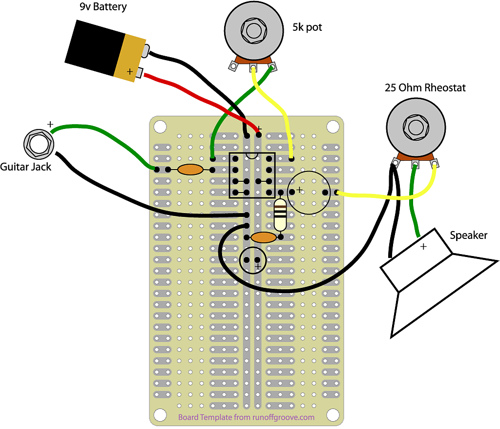 The directions where a little difficult to understand, they assumed that you have a good knowledge of circuit diagrams. With the help of of this diagram it should be too hard to figure out what to do. I probably would not have gotten it working with out that diagram.
Instead of using a 1/4 mono phone jack I used a mono head phone jack that connects easily to my IPod. I removed the potentiometer, it just isn’t needed for a IPod amp.
A full size schematic and directions can be downloaded from MAKE’s web page. If you run in to problems feel free to leave me a comment I might be able to help you or try the MAKE forums
Parts list
- A box of some sort or another
- Toggle switch, single pole single throw
- 9V battery
- 9V Battery connector
- 0.047µF capacitor
- 220µF capacitor (biggest)
- 0.01µf capacitor
- 100µf capacitor
- Hookup wire, 2 0 or 22 gauge AWG solid core is best.
- 5KO potentiometer (audio or log taper)
- 25-ohm (25O) rheostat
- LM386N audio amplifier
- 8-pin DIP IC socket
- Chicken head knobs (2)
- Prototyping PC board
- Speaker, 8O impedance
- 10O resistor
- 1/4 mono phone jack
Equipment needed
- Soldering iron
- Solder
- Pliers
Leave a comment